A plan in five moves
- Set the picture. Card 01, its shape in Card 02: type a width or a diagonal, set the distance, or drag the projector in the venue. Whichever side you hold, the other follows through the lens.
- Pick the machine. Cards 03 and 04: run "By the numbers" with your own lumens and throw figures, or pick a branded model and its real lens list. "Pick for me" chooses the lens whose range covers your geometry.
- Place it in the space. Turn on Move, drag the surface or the projector, and use Space limits to draw the hard box everything must live inside. The Resolve chips appear whenever the geometry breaks and fix it one legal step at a time.
- Light it honestly. Card 07: pick the ambient light, click a surface grade in the ladder, and the venue renders the picture at its real brightness on that grade.
- Take it with you. The plan on paper prints the full record; Copy the plan link packs everything into a URL; the carry seeds the configurator; Request a demo brings it to the real surface.
The cards run in planning order down the page: the picture and its distance (01), the shape in plan (02), the machine (03), its lens (04), solutions on a curve (05), the array (06), and what the light is worth on the surface (07). Controls that depend on a parent setting, the meter panel, the keystone tools, the space limits fields, stay out of sight until that setting is on, then slide in beside it.
 1
2
3
4
5
6
7
1
2
3
4
5
6
7
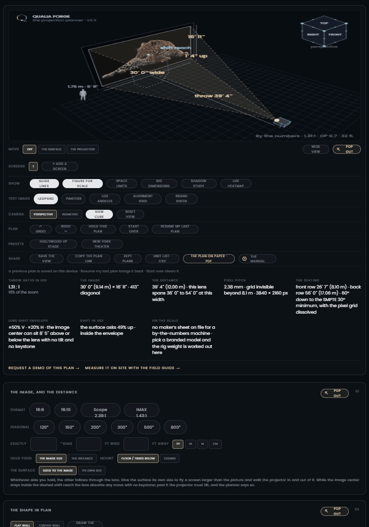
- 1The venue. Drag to orbit; everything lands here at its real geometry.
- 2The view cube: faces are drawings, corners are three-quarter views.
- 3Move and Screens: what your drag holds, and up to four plans in one scene.
- 4Show, Test image, Camera: the reading aids and what the beam carries.
- 5Plan, Presets, Share: undo, kept plans, the plan link, PDF and CSV.
- 6The readouts: throw ratio, image, distance, pixel pitch, seating, shift, weight.
- 7Cards 01 to 07 run below in planning order, picture to surface grade.
The venue and the camera
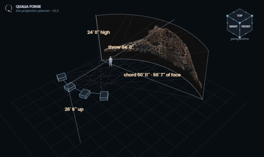
The dark viewport is a measured 3D venue. Dragging it orbits the camera and nothing else: objects never move by accident, only when a Move mode is on.
The view cube
The cube in the corner is the camera's compass, in the 3ds Max idiom. It turns with the venue; clicking a face, an edge dot, or a corner dot glides the camera to that view. TOP gives the floor plan, FRONT the elevation, corners the three-quarter views. The Perspective / Isometric switch changes the lens: perspective is a natural camera, isometric is a drawing-office camera where parallel lines stay parallel, so distances compare honestly anywhere in the frame.
Wide view and the floating stage
Wide view grows the venue over a dimmed page; Pop out lifts it into a window you can drag and resize by its corner grip, the canvas refitting itself to the window at the same field of view. Perspective stays perspective at every size: the camera never crowds in just because the canvas grew.
Reading aids
- Guide lines draws the throw triangle and dimensions on the venue.
- Rig dimensions adds the rigger’s numbers: lens spacing, lens heights, stack pitch (chapter 07).
- Shadow study puts a draggable 5′ 9″ walker in the beams and marks how close anyone can come to the surface (chapter 07).
- Figure for scale stands a 5′ 9″ person beside the surface.
- Space limits draws your venue's hard bounding box and flags whatever stands outside it, with a one-click "Fit inside the space".
- Test images change what the beam carries: Leopard for sharpness, Panther for the black floor, Los Angeles for warp and seams, Brand sheen for color against ambient.
- Hold this plan photographs the current figures so the readouts compare everything you try next against it.
Moving and rotating in 3D
Turn on a Move mode (The surface or The projector) and three grammars become available at once. Use whichever suits your hand.
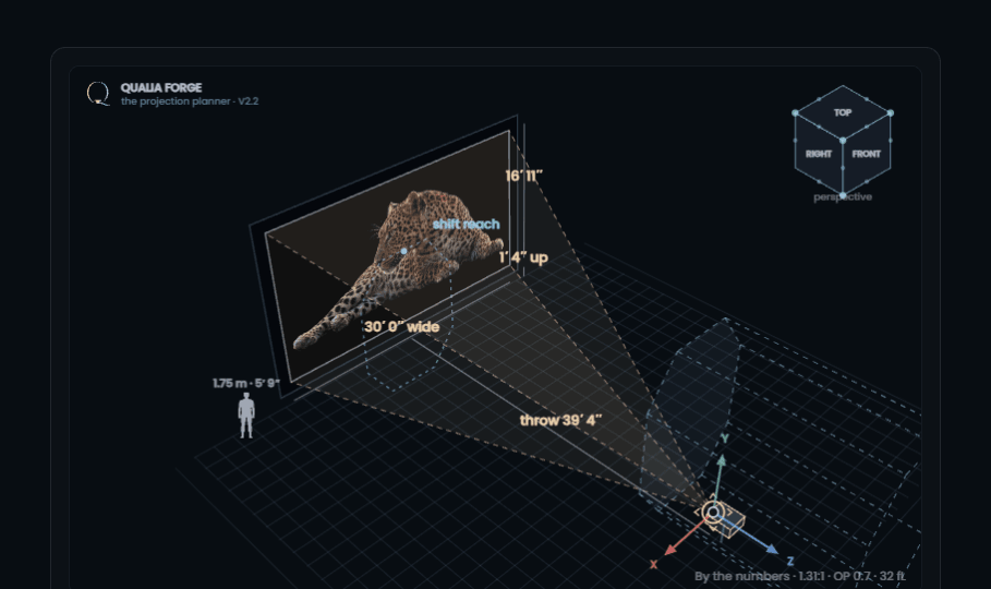
With the projector in hand, the venue also draws the available range: a pale blue volume marking everywhere the projector can stand with the lens still serving the surface square, no tilt, no keystone. It is built per machine and per lens from the real figures: sideways and in height from the lens-shift envelope (with the cut corners honored, since full vertical and full horizontal shift are never available together, which is why its cross-section is an octagon, not a box), and in depth from the zoom span at the current image size. It stays up while you drag, faded so it never hides the work, and the Guide lines chip turns it off with the rest of the linework.
Free drag
Dragging the object moves it in the floor plane: toward and away walks the throw, sideways walks it off axis. Shift + drag moves vertically: the rig rises and falls, the lens riding with it. With the surface selected and the beam decoupled, Shift + drag walks the surface in depth instead.
A canvas larger than the picture
In card 01, give the surface its own size and it becomes a canvas: a physical screen larger or smaller than the picture, with the image lighting only the section it covers. Picture and canvas then move independently: Move: the surface walks the canvas itself (drag, arrows, or typed coordinates), while the position sliders, the projector, and lens shift walk the picture across it. Overhang is called out in the readouts, and a decoupled beam roams the canvas torch-like, exactly like content playing across one section of a wide scrim. If the picture and canvas drift apart, Resolve to the canvas puts them back together in one click: one centered projector sized to fit, or the right count of blended landscape or portrait tiles filling it edge to edge, rigged on the ceiling.
The XYZ arrows
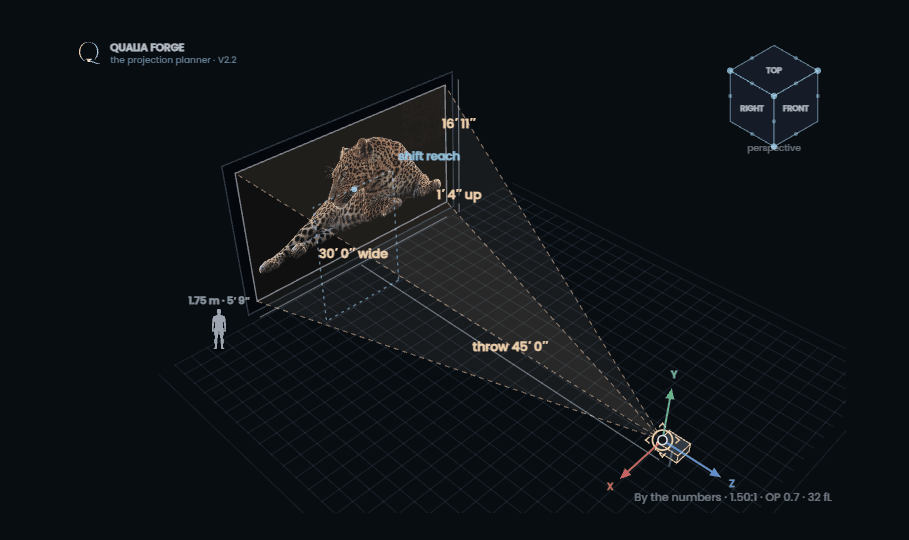
A move gizmo stands on the active object: X runs across the venue, Y runs up, Z runs along the throw. Click an arrowhead and drag: the move locks to that one axis no matter how the camera is turned. The surface shows X and Y, plus Z when the beam is decoupled; the projector and free-placed units show all three.
The rotation rings
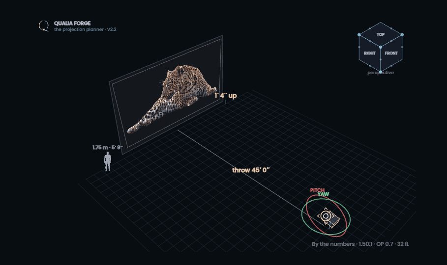
Press R or click Rotate the projector and the arrows become rings: the red ring pitches, the green ring yaws, and the blue ring rolls the chassis about its own aim (90° of roll is a portrait mount). Grab a ring and drag along it; the body turns at about a fifth of a degree per pixel, whichever way the camera faces. Right-drag or Alt + drag anywhere on the body does the same without the rings.
Rotate the surface
The screen itself rotates the same way. With Move: the surface on, the chip reads Rotate the surface (or press R) and the same three rings land on the screen: rake it back, turn it, bank it, ±80° of yaw and pitch, ±180° of roll, or type the angles in the coordinate row. The first turn quietly decouples the beam, freezing it exactly as aimed, because a rotated screen and a married throw cannot both be true: from there the picture lands as the true ray-cut of the beam on the raked face, keystone measured against the screen’s real angle, coverage clipped in the screen’s own plane, and the brightness gradient following the face’s real normal. Hand pins ride the rotated face, and the warp desk shows it square-on, as a commissioning tool would. Reset position squares everything again.
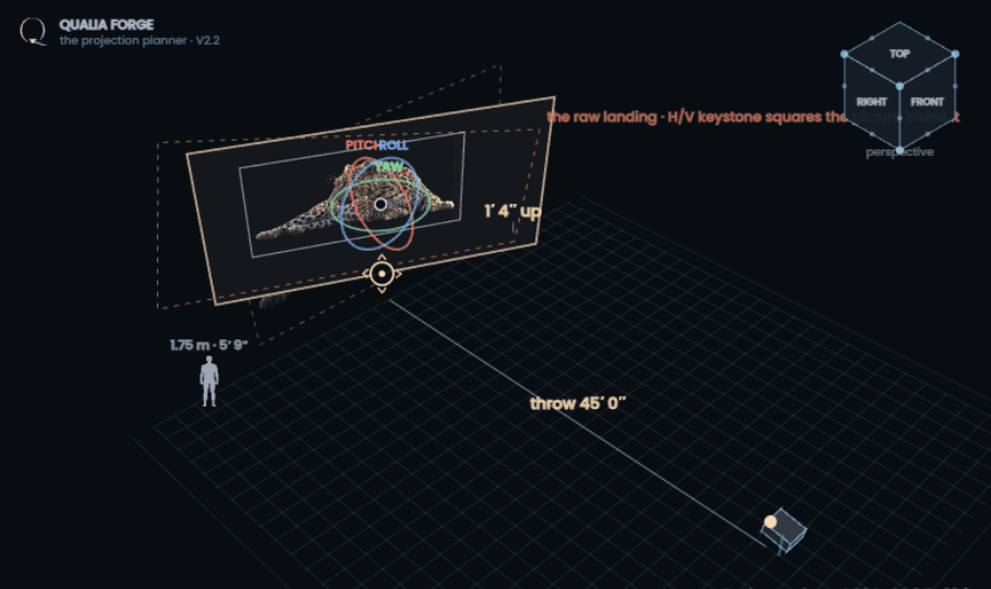
Type it exactly
Whenever Move is on, a coordinate row sits under the venue: X, Y and Z in your working units, plus yaw, pitch and roll in degrees where rotation applies. Type a value and press Enter; the object goes exactly there, inside the same limits the drags respect. The row relabels itself for whatever is selected, and it is the precision path: drag to explore, type to align.
The decoupled beam
Normally the planner keeps the projector and the surface married: move one and the optics follow. Decouple the beam breaks the marriage. The beam becomes a torch out of the body: a real light cone that goes wherever the chassis points, spreading and dimming with distance. Only where it crosses the surface does a picture land; the rest washes the back wall as raw light, drawn dashed.
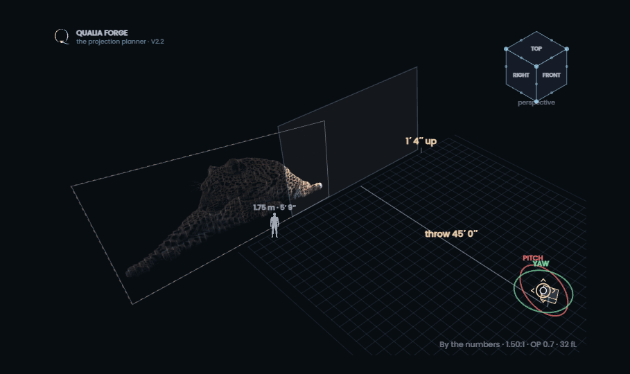
Once decoupled you can move the projector and the surface fully independently, in depth too, and rotate the projector freely: ±80° of yaw and pitch, ±180° of roll. The readout under the venue tells you which optical regime the aim is in: inside the lens's shift envelope the offset is carried optically and the picture stays square; past the envelope the chassis is physically tilted, and the readout states the tilt angle and what it costs. A stacked rig decouples too: one converged raster, the whole tower turning with the beam, the summed lumens carried through every readout. Only true multi-tile arrays (blend grids and free-placed rigs) stay married to their tiles, because there each unit owns its own beam.
Why the regimes matter. Lens shift moves the picture without touching its shape. Tilt changes the angle the light arrives at, and the picture keystones. Both are legitimate; the planner just refuses to hide which one your geometry is using.
Keystone: the three corrections, and what each one costs
When a projector cannot reach its surface with lens shift alone, it must tilt, and a tilted beam lands as a wedge: wider where the light travels further, brighter where it lands nearer. That wedge is keystone. Squaring it back up is a raster operation, and the field knows three digital routes. The planner models all three, and it only offers the ones the selected machine actually carries.
The three routes
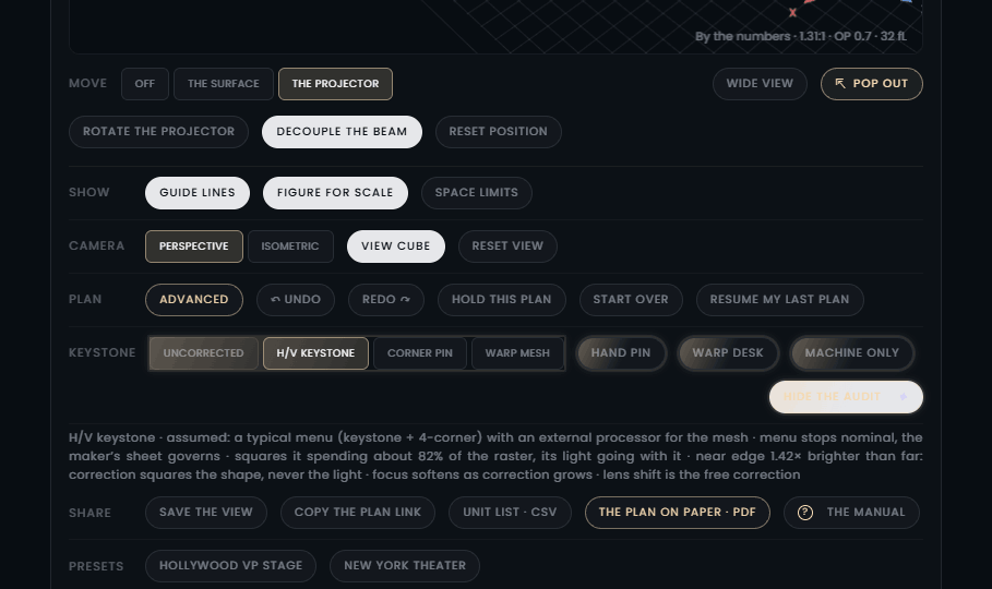
- H/V keystone, from the projector menu. The oldest and simplest: one dial per axis. It squares a pitch or yaw error on a flat face, and it cannot take roll out. Where the maker publishes stops, the planner enforces them: Panasonic caps keystone per lens (±45° vertical on the standard glass but only ±15° on the 0.65–0.85 zoom, +5° on the mirror UST, and V plus H together never past 55°), and the JVC reference machine corrects vertically only. Ask past the stop and the planner says so: the picture stays keystoned until an external processor or a re-rig covers it.
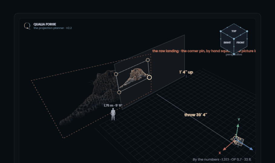
- The corner pin: each image corner placed by hand, a full homography. It squares any error a flat face can produce, roll included. Most large-venue machines carry it under their own name: Quick Corner (Epson), Cornerstone (NEC 3D Reform, Digital Projection), Corner Fit (BenQ), Corner/Pincushion (Panasonic).
- The mesh warp: a grid of nodes across the raster. Everything the pin does, plus curved faces, and the only route onto a dome or a drawn wall. Christie embeds it as Twist (87 grid points on board, 1,500 with Twist Pro); Barco Pulse carries keystone, 4-corner and bow on board with full node warp through Projector Toolset; Panasonic extends its menu with the free Geometry Manager Pro grid; Epson calls it Point Correction. Machines without a mesh need an external warp processor or the media server.
And one machine to remember: the Sony VPL-GTZ380 carries no digital geometry at all. Its installation budget is a very large shift envelope, and the planner will tell you exactly that when you tilt one.
What every route costs
All three spend the same coin. The correction pre-shrinks the raster inside the panel, so pixels park black outside the picture and their lumens leave with them; the readouts and the printed plan give the percentage spent. The black floor still lands as the whole wedge. Focus softens as correction grows, a warning Panasonic prints in its own spec file. And no route levels the light: correction squares the shape, never the illumination, so the near edge of a corrected picture stays brighter than the far one by the inverse square of the throw and the angle of arrival. The planner draws that gradient on the surface and states the near-to-far ratio. One more honesty for the fully unlocked rig: decoupling frees the projector from the throw triangle altogether, so the planner also carries each lens's nominal focus span (the makers quote roughly 70 to 1,000 inches of picture); park the machine outside it and the picture lands soft, drawn with its defocus and flagged in the readouts.
Building the case in the planner
- Place the surface where it really has to go: drag it high, low or off to the side, past what the shift readout says the lens can reach, or decouple the beam and rotate the projector body directly: yaw, pitch and roll rings, the keystone following honestly.
- The amber wedge appears: the raw beam, exactly as it lands. The Keystone row wakes in the tools stack, directly under Plan, announcing itself with a short pulse: Uncorrected, H/V keystone, Corner pin, Warp mesh, then Hand pin, Warp desk and the machine/processor switch. It also stands ready whenever the beam is decoupled or Free placement is on, tilt or no tilt. Routes the machine does not carry are greyed with the reason; the planner pre-picks the lightest sufficient route and names the real tool. The full audit sits behind the peach More ✦ toggle to keep the row clean, and surfaces itself uninvited when something is genuinely wrong.
- Uncorrected shows the trapezoid as thrown, strip-lit by range and arrival angle, with the plan rectangle dashed inside it. Any correction route shows the squared picture instead, with the raster and light price and the residual brightness gradient.
- Read the audit line. It checks the ask against the machine's own stops (per lens where the maker publishes them), flags a roll error handed to H/V keystone, and prices the raster spend and the near/far light ratio.
- Decide like an installer: accept the cost, as real venues often do, or click a Resolve chip: slide the surface into reach, re-rig the height, or walk the projector across, each one a legal no-keystone fix. The printed plan carries the tilt, the route, the tool and the spend, per unit on arrays.
The hand pin and the warp desk
Hand pin puts the four corners in your hands, the Quick Corner way: drag them straight on the picture in the venue, per unit on a free-placed rig. Warp desk opens the flat commissioning view every warp tool draws: the surface square-on, the raw footprint, the raster and its pins, with the venue's own content or the alignment grid mapped through the true projective chain and lit by the same range-and-angle physics as the venue. Click a pin and type its offsets, nudge with the arrow keys (5 mm a press, Shift for 50 mm), snap the lot back square, copy one unit's pins to the whole rig, or save the offsets as a pin set and recall them later; sets travel with the plan link. Every move is audited live: a corner cannot leave the raw beam, crossed pins are refused, and the raster spend, the light loss and the near/far gradient track the pins as they go.
Machine only / + external processor sets whose rules apply. Machine only enforces the selected projector's own engine, its published stops, and greys the routes it does not carry. Adding the external processor puts a warp box upstream: every route opens on every machine, no menu stop applies, and the raster becomes the only budget, exactly the media-server case.
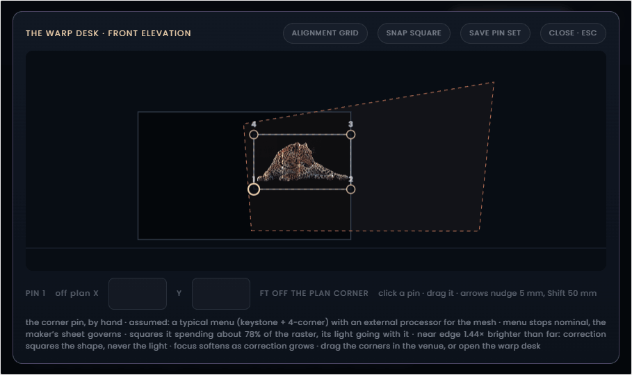
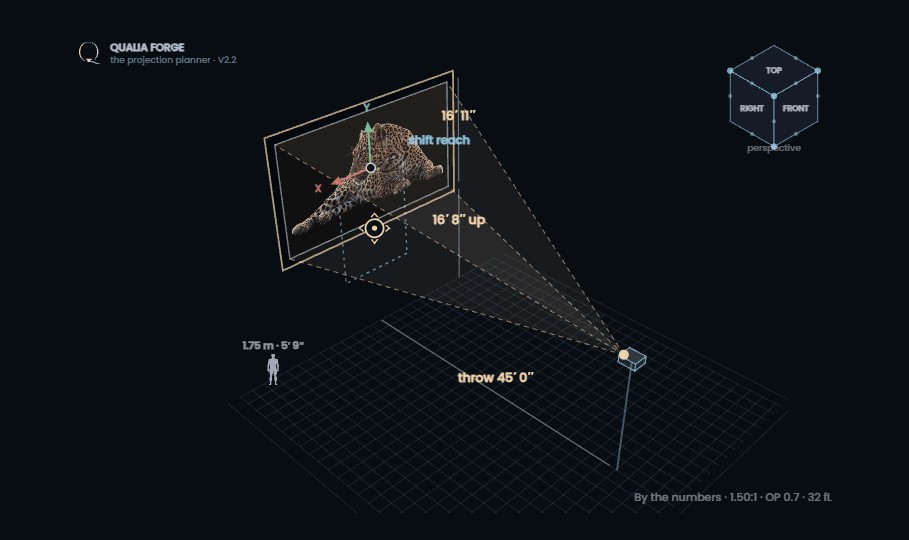
Rule of thumb. Shift first, rig second, digital geometry last. Shift is free, moving the rig costs a ladder, and every digital route costs pixels, light and focus forever. When you must correct: menu keystone for a one-axis error, the pin for a compound or rolled one, the mesh for a curve.
Arrays, blending, stacking, free placement
Card 06, Open the array, opens multi-projector work; Back to one projector in its header closes it again, columns, rows and stack reset to one. The grid picker sizes the mosaic the way you would size a table: hover the cells to preview the shape, click and the array is set, the caption spelling out units, picture size and tile size. The Columns and Rows buttons still step one axis at a time. Either way, columns and rows tile one wide picture from several machines; the overlap slider sets the blend band, where two projectors ramp against each other and sum to one tile's light. Chassis and screen orientation are independent: portrait tiles hug tall walls, and a mismatch parks unused pixels black, with the readouts saying how many.
Freed units answer to the whole scene: swing one toward a neighboring screen and its light lands there, drawn as a warm patch on that screen’s face labeled with the unit that threw it, the unit’s own wall still blocking whatever it catches first.
Stacks, up to eight
Stacking converges machines on the same frame for brightness: the 1 / 2 / 3 buttons cover the common cases, and the count box beside them takes any stack up to eight. Towers climb four chassis high; a fifth unit starts a second tower alongside, with a gap between the columns, the way riggers actually build them. Every chassis in the stack throws from its own lens, so the venue draws one cone apex per body, all converged on the shared landing; the light is one picture at the stack's summed lumens, which is exactly what a warped, converged stack delivers. To aim or tilt a stack as one rigid rig, turn on Free placement and rotate it (rings, right-drag, or the yaw and pitch sliders), or decouple the beam: the whole tower rides the beam frame as one piece.
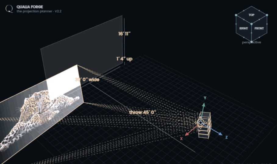
Free placement releases every unit from its plan seat: select one in the venue or step with Previous/Next, then drag, lift, aim and roll it with the same grammar as the single machine. "Aim at its tile" points it home; "Snap all to plan" rebuilds the mosaic. The Blend map chip appears the moment the rig has two projectors, flat grid or curved wall: every unit's coverage in its own hue, the bands layering brighter where they share, each tile numbered so unit 2 in the venue is unmistakably unit 2 on paper. And every free-placed unit carries its own geometry: the Keystone row, the audit and the hand pins all work per selected unit, and "Copy pins to all units" on the warp desk propagates one unit's offsets to the whole rig, tile-relative. Free placement is also where the focus physics follows each unit alone: drag one off its plan throw, past the lens's focus band, and its picture softens on the wall from its own lens-to-landing distance, with the readout saying so.
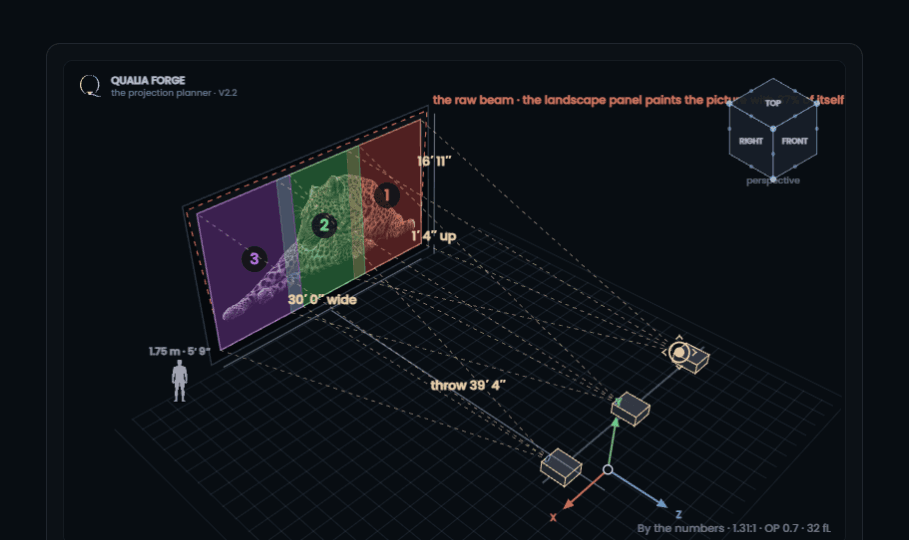
The blend tax. Inside a band the picture is only as bright as one tile, but every unit's black floor lands across its whole footprint, so each seam carries a second black floor. Fewer, wider blends are easier to align; more, tighter tiles carry more pixels. The curved-wall solutions rank these trade-offs for you.
The scene: screens, shadows, and the rigger’s numbers
Up to four screens in one scene
The Screens row above the tools puts up to four complete plans in one venue. Each screen is everything this manual describes, surface, projector, lens, array, grade and geometry, with its own seat in the space: an X and Z position and a facing angle. 0° faces the audience, 90° stands the screen along the right-hand side, −90° along the left, so two walls at −90° and 90° face each other across the venue, the classic corridor of light.
The numbered buttons choose which screen the cards drive; the others sleep in the venue as ghosts, and clicking a ghost or its name tag wakes it. + Add a screen copies the current plan and seats the copy alongside, so a matched pair takes three moves: add, type the facing, type the seat. Undo, the plan link, the printed plan and the CSV all carry the whole scene: the paper record adds a screen-by-screen summary, and the spreadsheet a screen column with each seat.
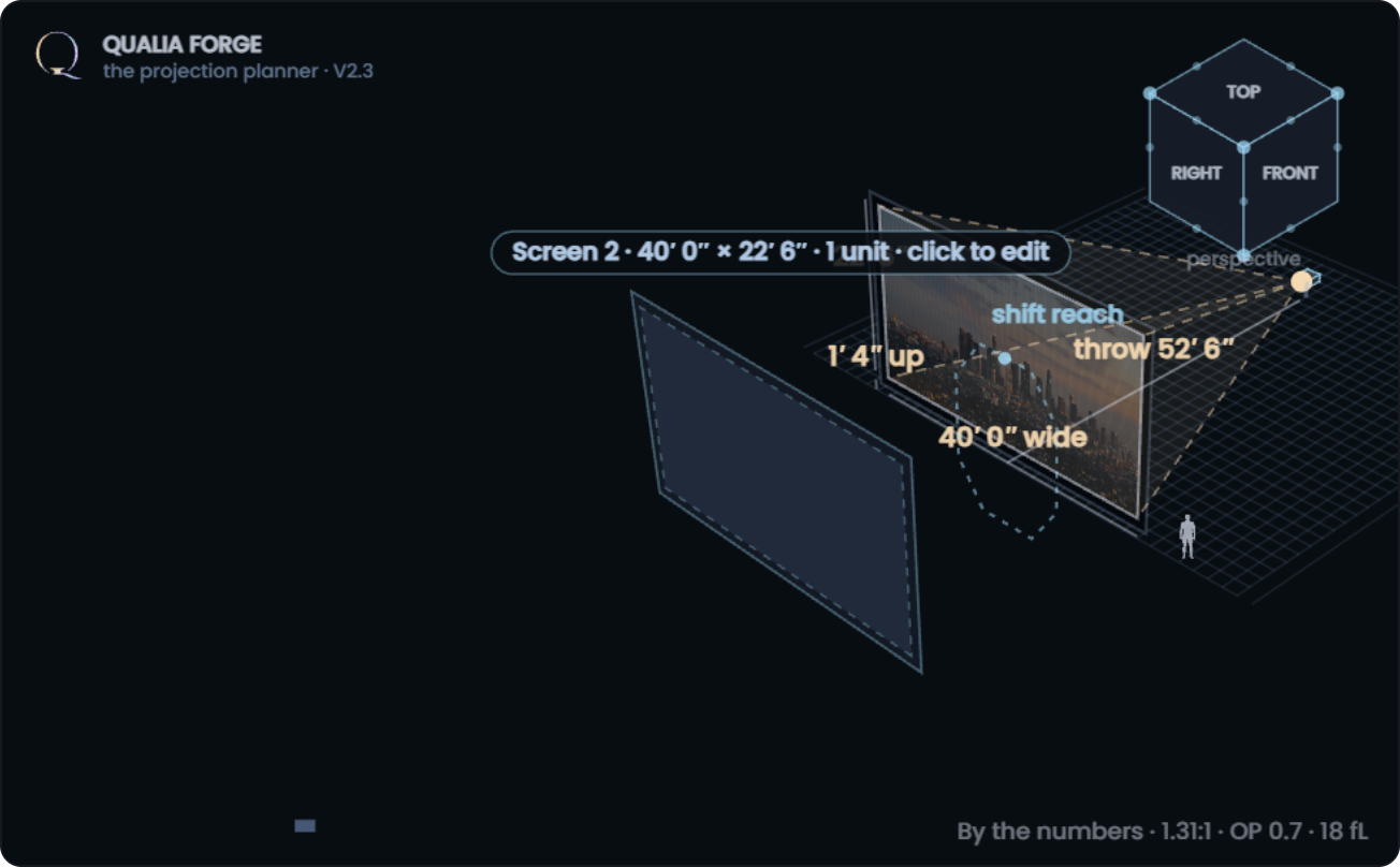
The light meter: the lux heatmap
Lux heatmap in the Show row paints illuminance straight onto the surface, worked per point from each lens’s true distance, arrival cosine, zoom and blend ramp: lumens over one tile’s area anchor the scale at the plan throw, then the inverse square reshapes it point by point, with a nominal 10% corner falloff standing in for lens rolloff. Peak, average, minimum and min/peak uniformity read under the venue, hot and cold spots are marked on the face, and a legend carries the scale. It works on flat walls, arrays and drawn curves alike.
Raw field / Flat field are two different instruments. Raw is the bare physics above, honest about throw, stacking and offset. Flat field is the calibrated delivery: a projection lens is engineered to land uniform light on its own focus plane (the ANSI uniformity spec), so on a square-on flat wall it reads even edge to edge, and what remains is geometry alone: keystone stretch on tilted or aimed units, depth variation on drawn curves, and the blend ramps. Raw shows why; flat shows what a dialed-in show measures.
The map is anchored on exposure. On auto, the target works out what a clear picture needs right where you stand: reference white, held seven times above the ambient veil this grade returns, so the mark rises with venue light and falls on deeper grades. Where the delivered light lands under it the map fades, washed the way the audience would see it; where it lands over, it runs hot toward red, and the neutral band reads exactly right. The legend carries the needed figure and the readout states how far the average sits from it. Type your own lux or fL to hold a house number instead, or type 0 for the plain absolute scale.
The meter’s settings live in a small panel that slides in under the Show row while the heatmap is on, grouped and labeled: lens model, the gate, the venue, what it reads, and the target; the × in its corner switches the heatmap and the meter off together. Three more switches make it a working instrument. Blended white / Open gate: blended sums each band to one tile’s light, the calibrated picture; open gate leaves the ramps off, the roughly-double band a meter actually reads during alignment. Dark venue / With ambient adds the held ambient from card 07, the incident meter’s real number with the lights on. Lux / fL on this grade switches between light arriving at the face and light leaving it toward the audience, tied to the planner’s calibrated luminance model.
Sleeping screens still shine
A ghost screen is never dark: its rig draws faint dashed cones from every lens to its own tile, so a four-screen scene reads as four working projections at a glance, not one live wall among gray ones.
Light that crosses screens
Beams answer to the whole scene. Aim a freed unit past its own wall and its light lands where it truly falls: on a neighboring screen it draws as a warm dashed patch labeled with the unit that threw it. When that neighbor stands between a projector and its own picture, the patch reads lands here first · shadow behind and the warnings name the shadowed picture with the fixes: slide either screen, re-aim the unit, or plan around the cut.
Rig dimensions
The Rig dimensions chip in the Show row draws the numbers a rigger asks for first, straight on the venue: lens-to-lens spacing center to center, labeled once with “every pair” when the row is uniform; each distinct lens height dropped to the floor; and the vertical pitch between lenses inside a stack. These are lens positions, not chassis dimensions or mounting hardware, so the figures hold whatever frame the units ride in.
The shadow study
Clients ask one question about walk-up surfaces before any other: how close can somebody get before they block the picture? The Shadow study chip, off by default, answers it two ways at once. A 5′ 9″ walker appears in the venue for you to drag anywhere on the floor; every lens whose beam they actually stand in casts their true silhouette onto the surface, sized and softened by the same projection geometry as the picture itself, so a walker near the wall throws a small hard shadow and a walker near the lens a large soft one. Stacked lenses each cast their own partial shadow, which is why stacking is also a shadow strategy: the other units half-fill what one body blocks.
The dashed floor line is the summary: where the beam’s lower edge crosses head height. On a ceiling rig the readout states how close a walker can come to the surface before entering the light; on a floor rig thrown up over the audience the clear zone reverses and sits against the wall; and when the beam crosses walking height the whole way, the planner says so plainly instead of drawing a line that does not exist.
The walker moves two ways. Drag them anywhere on the floor, or click them and a small step pad opens at their feet: four arrows that walk the figure in quarter-meter steps, toward the surface, away, left and right, with the cast and the floor line answering every step. Click anywhere else and the pad puts itself away.
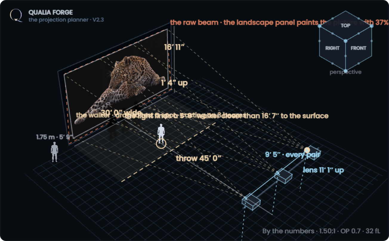
The rig on the floor
A single-row blend no longer has to ride at image height. With the Mount switch on Floor / truss below, the whole row stands on floor stands, every lens low, and the picture rides up on vertical lens shift: chassis square, no keystone, the beams fanning up from the low lenses. The shift readout prices the ask against the envelope, and when it runs out, Raise the projector rig to fit lifts the stands exactly as far as the lens needs. Drawn and curved walls take the same call: switch the mount and the fitted rig steps down from the ceiling truss to floor stands, every unit still square to its tile in plan.
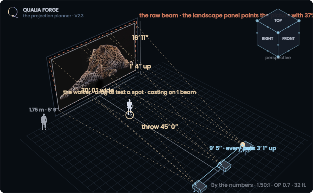
On the scale
Pick a branded machine and the readouts add On the scale: the maker’s published body weight, without lens, multiplied across the rig, per body, per stacked position and in total, in kilograms and pounds. It is deliberately narrow: bodies only. Rigging frames, projection cages, enclosures, hoists and cabling are not included, and every point load is confirmed against the maker’s current sheet at quotation. Figures marked “about” are nominal, pending a sheet check. The weight rides along in the printed plan and in one column of the CSV.
Curved walls and Draw the plan
Switch the shape to Curved and the wall becomes a chain of straight and arc sections, editable in the shape card. Draw the plan opens a drawing board: sketch the wall in one pass, left to right, or start from an L, U, Arc or S template, and the stroke snaps to true lines and arcs with their measurements.
Then refine it like a Bézier tool: drag a point to stretch, pull a diamond handle to bend a section through your cursor, and add a point three ways: the Add a point chip arms one click, a double-click on the line drops one right there, and a selected section offers "Add a point in the middle". Corners can be filleted or chamfered at the size you type. Accept the shape and the venue builds it: the rig moves to the ceiling, the projector count is fitted, and five ranked ways to light the shape appear, from the lean rig to the ultra dense one.
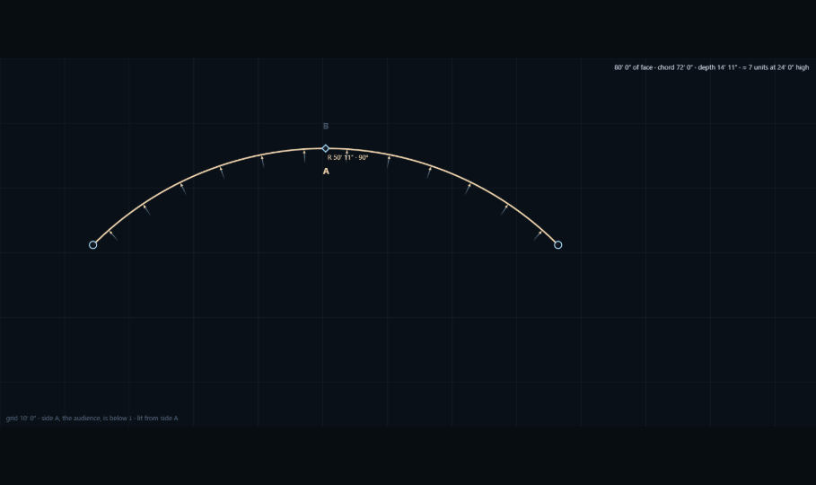
A curved wall is solver-seated: every projector stands square to its own strip of the face, so the Move switch is replaced by the one hand control that keeps the physics honest, turn the wall. Type up to 90° either way and the whole drawn shape rotates in plan; the rig re-seats itself on the turned face, every unit finds its strip again, and throws, focus travel and arrival angles all recompute. Picking a preset or drawing a new wall squares the turn back to zero.
The board navigates like a map
The mouse wheel zooms about the cursor, the span chips set a working scale, and Fit the view brings everything drawn back on screen when a point wanders off the edge. The drawing, the background trace and the venue frame slide together, so zooming never moves a wall in the venue.
Each screen keeps its side
Lit from is remembered per screen: side A, side B, or both faces each travel with their own surface through screen switches, kept plans and plan links. Change the side and press Accept and the rig crosses to the face you asked for, even when the shape itself did not change.
Every surface on one board
With more than one screen in the scene, the board becomes the venue’s shared plan. The surface in hand draws solid; every other screen waits as a pale dashed line with its rig marked, exactly where it stands in the venue. Draw the new wall among them and Accept seats it right where you drew it, position and angle included; moving a whole selection and accepting re-seats the wall the same way. The Surfaces chips above the board, or a click on any pale line, change hands, and + New surface adds a screen with the pencil already in yours.
Upload a plan
The wall does not have to start under your pencil. Upload a plan on the drawing board, or a file dropped straight onto it, takes three kinds of source. An SVG is sampled along its longest path and fitted into sections exactly like a freehand stroke. An ASCII DXF from any CAD tool is read entity by entity, lines, polylines with their bulges, arcs and splines, chained end to end where their tips touch, and the longest chain fitted. A picture, a photo or a scan of a plan line, lands on the board as a backdrop; the planner traces the strongest single dark line it can read and fits that, and when no clean line can be read it says so and leaves the picture under your pencil, so drawing over the backdrop is always the fallback that works.
Two habits make imports land well. First, imported files carry no trustworthy units, so type the real developed length into the face measures and the whole shape, backdrop included, scales to match before you accept. Second, expect to edit: a closed outline arrives whole, and you Remove the sides you do not need; a wobbly photo trace is a starting chain of points and handles, not a verdict. Shoot pictures square-on, dark line on light paper; a binary DXF needs saving as ASCII (R12 or later) first, and a PDF wants exporting as an image before it comes in.
Working the drawn wall: solutions, blends, trade-offs
Shapes that cannot be lit from inside
Some drawings are honest dead ends: a hairpin with its legs a few feet apart, lit from inside, puts the opposite face between every lens and its tile, and no lens or warp shoots through a wall. The planner says so instead of pretending: those beams draw red in the venue and the warning opens with "Not solvable as drawn", naming the free depth against the lens’s minimum throw. The ways out are the real ones: light the shape from the other face, open the legs, or plan a separate rig per leg. In multi-screen scenes the same honesty applies between screens: a screen standing inside another rig’s beam catches the light first, the patch is labeled and the warning names the shadowed picture.
Accepting a drawn wall is the start of the work, not the end. The venue builds the shape, moves the rig to the ceiling, fits a projector count, and then hands you three levers and a ranked list. This is how to work them.
The five solutions
In card 05, after the lens, the planner ranks five valid ways to light the shape with the chosen machine, the fitted rig first, alternatives after: from the lean rig with the fewest units to the ultra dense one. The figures carry the argument, so read them the way an integrator would: pixel density against how close the audience stands, per-tile brightness against the ambient you set, focus travel against the sag of the curve, and the seam count against alignment labor on a ladder. Use this applies a row to the venue; nothing is committed until you like what lands. When two rows read close, pick the one with fewer seams: pixels are bought once, blends are aligned every load-in.
Units along the face
The count is the master trade. One unit fewer means wider tiles: fewer seams, more focus depth on the arc, but lower pixel density and each machine's lumens spread across more face. One unit more means narrower tiles that hug a tight curve, higher density and brightness, and one more seam to align. Fit the count for me sets the count so each tile is exactly what one panel paints at the current band height and overlap; start there, then push one step each way and watch the warnings.
The rig layout
Follows the wall traces the rig along the curve, each unit standing off its own tile no further than the local center allows: compact, and the beams stay short. Cross shoot stands each unit at full throw on its tile's normal, so on tight curves the beams cross the venue and buy throw length: brighter edges, better focus on deep arcs, but the cones fly through the space, so check them against scenery, trussing and follow-spot lines before committing. The per-unit table notes when a unit is held at its lens's minimum throw: the corner turns tighter than the machine can stand back from, and the cross-shoot layout is usually the cure.
Blending on the curve
Curved rigs blend along vertical seams only; every tile runs full height. The overlap slider prices the bands: wider bands are kinder to align on a face that curves through them, but each carries the second black floor, so deep grades matter more as bands multiply. Turn on the Blend map the moment the rig has two units: each unit's coverage in its own hue, the shared bands reading brighter, tiles numbered so unit 3 on the wall is unit 3 on paper. The Panther test image is the honest check: if the seams read milky on it at your ambient, they will read milky on show black.
Which face carries the picture
The lit from chips on the drawing board choose the side: Side A where the audience stands, Side B from behind the wall, or Both, the Transparent Scrim setup where each face carries its own image. Lighting from behind flips concavity: what you drew as a bowl lights as a dome, and the solver re-seats the rig on the far side.
Height, base, orientation
Band height and base-off-floor size the lit band itself; tall bands flip the fitted chassis to portrait automatically, narrow footprints hugging the curve. Stacks work on curves exactly as on flat walls: the count box adds brightness per station without touching the tile geometry. And when the venue's geometry will not meet the wall square, turn the wall (chapter 07) rotates the whole face in plan and lets the solver re-seat everything.
The physics that surprises people
| What you see | Why it is correct |
|---|---|
| Zooming wider makes the picture dimmer | Zoom holds the distance and changes the picture size. Brightness follows area, not distance: the same lumens over four times the area is a quarter of the light. |
| Moving the projector closer does not brighten a held picture | With the image size held, the lens zooms to compensate: same lumens, same area, same light. |
| A tilted unit is brighter on one edge | Inverse square at work: the near edge of a keystoned footprint can land visibly more light than the far one. The per-unit table quotes the ratio. |
| Blend seams look milky on dark content | Two black floors ride in every band. The Panther test image shows it plainly; deeper grades hold it down. |
| A brighter surface grade reads worse in a lit venue | The grade returns the venue's light along with the projector's. The ladder runs your machine across every grade at your ambient level so the trade reads in numbers. |
| A stack of eight is one picture, eight times the light | Stacked machines converge on one raster, so lumens sum while size, pixels and keystone stay those of a single unit. Columns and rows grow the picture instead; only stacking grows the light. |
| A rotated screen keystones a square beam | Keystone follows the angle between beam and surface, whichever one moved. Rake the screen 20° and a shift-squared throw lands exactly as keystoned as a 20° chassis tilt onto a square wall. |
| A unit dragged off its throw goes soft | A lens holds focus over a finite span. Park a free-placed unit past it and the picture lands, but soft: the planner draws the defocus and says so. |
| The front row is further than expected | Two limits: the pixel grid must have dissolved (about 3,400 × the pixel pitch) and the picture should stay under 60° of width. The seating readout applies both. |
Stand in front of it. Every row above is something you can watch happen on a real surface at the Hollywood demo facility. Bring your plan link; request a demo and we will run your plan at your ambient, on your grade.
Saving, sharing, printing
- Copy the plan link packs the entire plan, drawn walls and placed units included, into a compact URL: bookmark it, paste it into email or chat, reopen it anywhere. Send the plan does the sending for you: it opens your mail app or the device share sheet with the link ready to go, and whoever receives it opens the exact plan, live and editable, in their own browser.
- Auto-resume. The planner remembers your last plan on this device and picks it up when you return. Start over clears the slate.
- Kept plans puts named saves beside the Share row: name the plan, press Keep it, and it waits on this device, drawn walls, screens and placed units included. Up to twelve keep; each reopens with one click, and the × forgets it. Plan links travel; kept plans stay home.
- The plan on paper · PDF prints the full record: plan, elevation and isometric drawings, the optics, the geometry toolset in play, and one line per projector with position, aim, throw, keystone route and raster spend, pins, and blends. Arrays add a rig-spacing block: lens-to-lens step, row-to-row step, the rig spread first lens to last, and where the first lens center sits, the rigger’s tape-measure numbers. The illuminance heatmap prints square-on with peak, average, minimum and uniformity, and a light-meter block carries the dark-venue and ambient readings side by side. Multi-screen scenes add a screen-by-screen summary, and branded rigs their weight on the scale. It carries the plan link and the configurator seed, so paper reopens as software.
- Unit list · CSV downloads the per-unit table as a spreadsheet: positions in your units and meters, aim, lens and throw, geometry route and raster spend, pin offsets, near/far light and blend bands, one row per projector, ready for the integrator's own paperwork. Scenes with several screens list them all: each row carries its screen number, seat and body weight.
- 3D model writes the venue as a 3D file for your own software, right in the browser: OBJ with its MTL color library, DXF with one layer per object and Z up, GLB in meters for previz and game engines, or STL solids. Walls and screens, projector bodies, translucent beam wedges, the venue box and the ceiling rig line are each a named object you can toggle at the far end; chips choose the formats and contents, and with several screens the scope chip writes the whole venue or just the surface in hand. OBJ, DXF and STL come out in your working units, GLB in meters, the format’s own convention.
- Compare with LED carries this wall into the projection vs LED comparison page: effective pitch against the common tile tiers, the walk-up viewing model, and the honest setting-by-setting ledger, all computed on your plan, with a chip that brings you back here.
- Carry it into the configurator packs the optical case into a seed: picture size, grade, lumens, resolution, ambient and the blend grid; positions, aim and drawn walls stay with the plan link. On a decoupled throw with a correction applied, the seed carries the squared picture actually delivered, not the size first asked for. The configurator answers the surface question at real brightness, and its own seed comes back through Recall. The crossing is round-trip: the planner keeps your plan the moment you cross, and the configurator’s seed bar grows a chip that walks straight back to it, nothing reset.
- Save the view downloads the current venue frame as an image; Pop out floats any card over the page while you work.
Tips and tricks
Seeing clearly
- Measure in isometric, present in perspective. The drawing-office camera keeps parallel lines parallel, so distances compare honestly anywhere in the frame; switch back to perspective when a client is looking.
- TOP is a floor plan, FRONT is an elevation. Click the cube's faces for drawing views, edge and corner dots for the three-quarter angles; in isometric these are the drawings an integrator expects.
- Pick the test image for the question. Leopard for sharpness, Panther for the black floor and milky seams, Los Angeles for warp and blend geometry, Brand sheen for color against ambient. Most wrong conclusions come from judging black floor on a bright image.
- Stand the figure in the venue before arguing about size. A 5′ 9″ person beside the surface settles “how big is 300 inches” faster than any number.
- Read the red beams as a verdict. On a curved wall, beams that draw red cannot reach their tiles: the wall itself stands in the light path and the warning opens with "Not solvable as drawn". Fix the shape or the side, not the projector.
- Use the spill patch as a design tool. The warm lands here patch on a neighboring screen is real geometry: aim one freed unit across the venue on purpose and you have sketched a two-screen throw before committing a machine to it.
- Size arrays in the grid picker. Hover the cells to preview the mosaic, click to set it; the caption answers units, picture size and tile size in one line, faster than stepping Columns and Rows.
- Walk the meter before the meter walks you. Open gate + with ambient is what commissioning day actually measures: hand that heatmap to the projectionist and the on-site readings stop being surprises. Blended white is the picture the client sees; the difference between the two is the blend engine’s whole job, made visible.
- Click the walker for the step pad. Dragging finds the neighborhood; the pad’s quarter-meter steps settle the exact spot. “One more step back” in a client conversation becomes one click, repeatable and on the record.
- Guide lines off is the client view. The grid, the throw triangle and the dimensions vanish; Save the view then hands you a clean frame for the deck.
- Pop out the venue and let it float full-size while you work the cards underneath; every card has the same chip.
Placing with precision
- Drag to explore, type to align. The coordinate row under the venue takes exact X, Y, Z and angles; Enter commits inside the same limits the drags respect.
- The surface self-centers. Drop it within a couple of inches of the projector axis and it clicks to zero, so “centered” never means “almost”.
- Hold this plan before experimenting. Every readout then compares live figures against the held ones, including the light delta in plain terms. It is the fastest way to answer “did that help”.
- Draw the space limits first. With the hard box in place, every later move is checked against it, and “Fit inside the space” has something to solve toward.
- Undo is fearless. Forty steps over the whole plan and the camera is never touched, so orbit freely while you step history back and forth (Ctrl Z / Y).
- R is a mode flip, not a menu. Whatever Move holds, the projector or the surface, one key swaps its arrows for rings and back.
Light and lenses
- Brightness problem, stack; size problem, columns. Stacking multiplies lumens on one raster; columns and rows buy pixels and area. Mixing them up is the most expensive mistake in the trade.
- Click the ladder like a light switch. Each grade row relights the venue with that surface at your ambient; the same machine tells a different story at 1.5 lx and 150 lx.
- Distrust the “move it closer” instinct. With size held, the lens zooms to compensate and nothing brightens. Hold the plan, try it, read the delta.
- Flip on the external processor to preview what a media server unlocks on a stop-capped machine: every route opens, and the raster becomes the only budget. Then decide whether the box earns its rack space.
- Roll 90° is a portrait mount. On a decoupled or free-placed body, the blue ring turned a quarter is exactly how tall venues get portrait rasters without portrait product lines.
Arrays and commissioning
- Step units, do not hunt them. Previous / Next walks the rig in order; the blend map's hues and numbers keep venue and paper speaking the same names.
- Commission one unit, copy to all. Set one unit's pins on the warp desk, then “Copy pins to all units” propagates them tile-relative across the rig.
- Save pin sets like photographs. One set as commissioned, one after the re-rig; they recall onto the current plan rectangle and travel with the plan link.
- Nudge pins from the keyboard. On the desk, arrows move the selected pin 5 mm, Shift 50 mm: commissioning-grade precision with no mouse tremor.
- “Aim at its tile” and “Snap all to plan” are the safety net. Explore a free rig as wildly as the venue demands; home one unit or rebuild the whole mosaic in a click.
The drawing board
- Template first, freehand second. Start from L, U, Arc or S and pull it into shape; the fit is cleaner than sketching from nothing.
- Re-fit the same stroke. Faithful / Smoother / Simplest re-run the fit on the stroke you already drew; you do not have to draw again to change your mind.
- Hold Shift for square corners. Dragging a point with Shift snaps its legs to 45° steps, and “Square up” trues the straights to 15° afterwards.
- Drew it backwards? Mirror. The shape flips left to right with concavity preserved, which is faster than redrawing a wall you sketched from the wrong side of the plan.
- Fillet the corners you will actually build. A typed fillet or chamfer at the real radius changes the fitted count and the focus story; sharp paper corners flatter the plan.
- Draw the venue, not one wall. With two or more screens the board shows them all in one plan: sketch each new surface in relation to the ones already standing and it lands in the venue exactly where you drew it, angle and all.
- The board navigates like a map. The mouse wheel zooms about the cursor, the span chips set a working scale, and Fit the view brings everything drawn back on screen when a point wanders off the edge. A right-click on a point removes it, the same gesture family as the click that adds one.
- Trace the drawing you already have. Upload a plan takes an SVG, a DXF, or a photo of the plan; when the auto-trace misses on a messy picture, the backdrop stays and you draw over it. Set the real length before accepting.
Plans as documents
- The plan link is version control. Every variant you bookmark is a complete, reopenable plan, walls, units and pins included. Send two links, not one link and a paragraph.
- Paper reopens as software. The printed plan carries its own plan link and configurator seed; whoever holds the PDF can stand the venue back up.
- CSV is for the integrator. One row per projector with position, aim, route and spend drops straight into their paperwork; do not retype what the planner already tabulated.
- Keep before every big experiment. Kept plans are your working states, named for the venue and the day and held on this device; plan links are what you send. With a keep behind you, no rework is ever more than one click away.
- The configurator trip costs nothing. Carrying a plan across keeps it in the planner first, and the seed bar’s back chip returns you to the exact plan. Keep on this device holds the specification on the configurator side the same way.
Every key and gesture
The two tables below also exist as the key card: one printable, ink-friendly page for the desk beside the planner.
In the venue
| Input | Does |
|---|---|
| Drag | Orbits the camera. With Move on and the object grabbed: moves it in the floor plane (surface: in the wall plane). |
| Shift + drag | Moves the grabbed object vertically; decoupled surface: walks it in depth. |
| Right-drag or Alt + drag | Rotates the projector body: yaw with x, pitch with y. |
| XYZ arrowheads | Drag one: the move locks to that axis. |
| Rotation rings | Drag along a ring: pitch (red), yaw (green), roll (blue), about 0.2° per pixel. On the projector or on the surface, per the Move switch. |
| R | Toggles the rotation rings on the Move target: the projector (with free placement or a decoupled beam) or the surface itself. |
| Click the walker | With the shadow study on: opens the step pad; its arrows walk the figure in quarter-meter steps. Drag still works; clicking elsewhere closes the pad. |
| Pin handles | With Hand pin on: drag a corner of the picture; a move that leaves the raw beam, or crosses its neighbor, is refused. |
| Warp desk: arrows | Nudge the selected pin 5 mm; Shift takes 50 mm; Esc closes the desk. |
| View cube | Click a face, edge or corner: the camera glides to that view. |
| Coordinate fields + Enter | Sets exact X, Y, Z, yaw, pitch, roll. |
| Ctrl Z / Ctrl Y | Undo and redo the whole plan, forty steps, camera untouched. Cmd on a Mac. |
On the drawing board
| Input | Does |
|---|---|
| Draw a stroke | Left to right; on release it snaps to true lines and arcs. Faithful / Smoother / Simplest set how closely the fit follows. |
| Drag a point / diamond | Stretches a section / bends it through your cursor. |
| Shift while dragging a point | Snaps its leg to 45° steps: square corners fall into the hand. |
| Double-click the line | Adds a point right there. The Add a point chip arms one click for the same thing. |
| Shift + click points | Gathers several; a drag then moves them together. |
| Right-drag / Shift + right-drag | Box select / lasso select. |
| Arrow keys | Nudge the selection; Shift takes bigger steps. |
| Delete | Removes the selected points; their neighbors join. |
| Z / Y | Undo / redo the sketch. Esc closes the board without touching the venue. |